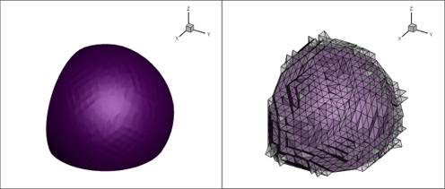
This webinar welcomes Dr. Scott Imlay, Tecplot CTO. He will discuss his research on visualization of higher-order CFD results. CFD code developers are adopting higher-order finite-element CFD methods due to their potential to reduce computation cost while maintaining accuracy. These techniques have been an area of research for many years and are becoming more widely available in popular CFD codes. The webinar content is based on Scott’s technical presentation at AIAA SciTech 2021. Note that this is preliminary research on adding higher-order element visualization to Tecplot 360.
Agenda (01:19)

- What are higher-order elements (1:42)
- Why use higher-order elements (3:30)
- Higher-Order Visualization Challenges (6:37)
- Basis Functions (8:32)
- Brick (Hexahedral) Sub-Division (12:06)
- Tetrahedral Sub-Division (12:51)
- Prism Sub-Division (13:32)
- Pyramid Sub-Division (14:38)
- Implementation (15:26)
- Results and Future work (17:33)
- Q&A (23:02)
We are looking for partners to try our prototype add-on or to provide data for testing. If you are interested, please contact us! The best way is through our website contact form, or email scottimlay@tecplot.com.
Online Resources
- White paper referred to in this video, Recursive Sub-Division Technique for Higher-Order Pyramid and Prism Isosurface Visualization
- Paper on GMSH referred to in the video
- Dr. Scott Imlay’s blogs on Higher Order Elements
Q&A From the Webinar
Is support planned for Tecplot file formats?
This is early research and we’ve not made definite plans for HOE support in the Tecplot file formats. We’re initially targeting reading CGNS format because it has an HOE specification. We don’t have definite plans for supporting HOE in Tecplot file formats yet. But we are looking at using the CGNS standard.
We are implementing this now as a Tecplot 360 add-on. The add-on is functional for showing the isosurfaces and the surface data. We are looking for research partners to collaborate with because we do believe that the industry will need HOE. You can contact me at scottimlay@tecplot.com.
Is the assumption that we have iso-parametric nodal data?
To rephrase your question, is our assumption that we allow curved elements of the same order as the basis function for this position (which would be iso-parametric)? The answer is yes, but that isn’t the solution for the long run. Our goal is to not require iso-parametric. We know that some people are doing linear geometry and higher order basis functions for the solution. Sometimes they have higher order basis functions for the geometry than they have for the solution. So it can go either way and we would like to support that. In the add-on we do use iso-parametric. If you want to create a linear element, in this case, put your edge-center nodes and location to give you a linear element.
Would you comment on how your algorithm relates to one in GMSH (algorithm for plotting high order solutions)?
I’m not super familiar with how GMSH does it. But my understanding is that GMSH also uses a subdivision technique. And it does not do it selectively for the isosurfaces. I think I should leave it there because I don’t want to state that I know more about GMSH than I do. Here is a paper about GMSH.
Did you consider using a Bézier representation rather than a heuristic buffer approach to make sure not to exclude extrema that cannot be seen via the nodal data itself?
It is a very good idea. We’ve thought about it, but we have not gone any farther than thinking about it. It is true that if you were to use Bézier representation, then they wouldn’t be nodal values anymore, but they would be the points in space that are used to adjust the shape of a B spline, for instance. And the minimum and the maximum are at those points. And so that way we could guarantee it.
The customers we have talked to are not using that as their basis functions. And so we would have to find a way to convert from more common basis functions to that before. If any of you are using those Bezier (or Bernstein polynomial) basis functions for not just the geometry, but for your solution data, I would really like to hear from you and learn more about it. Please contact me at scottimlay@tecplot.com.
How does the presence of higher-level (higher-order) elements affect interpolations onto a different grid in terms of fidelity and cost?
The add-on does not currently change the interpolations within Tecplot 360. If you were to interpolate to another grid, it wouldn’t take advantage of that at this time, but in the long run we certainly intend to do that.
In the future, the underlying basis functions would be utilized exactly. And your interpolation to any new nodes would be based on the higher-order basis functions. In terms of fidelity, that would mean it has the same fidelity as the higher-order solution.
The second part of your question is about cost. The cost is going to be higher per cell because it must solve of a nonlinear system of equations. If you have nonlinear geometry, it will have to solve a system of nonlinear equations to do the interpolation. But you have far fewer elements generally in a higher-order mesh than you do in a linear mesh. And so that means it’s quite possible that it would be cheaper overall than if you’re just going from a linear mesh to your new mesh.
How does Tecplot know the basis functions used for the higher-order solution? Does Tecplot expect solutions to be converted to a predefined format?
We support only the CGNS format, the quadratic or Lagrangian elements. If you are, for instance, converted into CGNS then it will have element type for each of the zones. And when we read that CGNS file, that’s how we know. The basis functions are effectively defined by the file format and element type.


