


 MENU
MENUResearch institute in Germany uses CFD simulations to help design cleaner gas turbine engines.
Climate change caused, in part, by heavy airplane traffic is a global concern. In Germany, a group of researchers at the University of Stuttgart’s Institute of Aerospace Thermodynamics is working on a project funded by the German Research Foundation and the Research Association for Combustion Engines to improve modern gas turbines by changing the geometry of turbine blade endwalls.
The end-users of the research findings — companies that manufacture gas turbine engines — hope to incorporate the results into their engine development process. The goal is to make gas turbines more fuel-efficient and help reduce pollutants. If this is achieved, the researchers will aid engine-manufacturers in building cleaner and more efficient gas turbines, which in turn will help the engine-users save money by reducing fuel consumption. Both of these positive outcomes are better for the environment and contribute to counter-act global climate change.
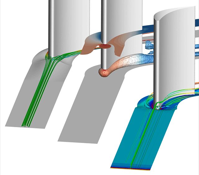
Tecplot 360 is used to visualize airflow around turbine blades and their endwalls.
Simulating Airflow and Analyzing Heat Transfer with CFD
So how are the University of Stuttgart researchers tackling this project? By using computational fluid dynamics (CFD) to simulate airflow in gas turbines and then analyzing heat transfer to the turbine blades and their endwalls.
Sven Winkler has been working at the Institute of Aerospace Thermodynamics since June 2010. He is one of the research associates who work under the supervision of Professor Bernhard Weigand on improving gas turbine heat transfer. “Simply put, our group conducts research of cooling techniques in gas turbines,” Winkler said. “The applications of our research are most useful in the development of jet engines and stationary gas turbines. I’m excited to be working on this project because of the benefits it will bring to our environment.”
In gas turbines, fuel is burned in a combustion chamber and the hot exhaust gases flow through the turbine rotor to produce power output. Since the exhaust gases are very hot, parts of the turbine rotor also become very hot and need to be cooled so they don’t melt. How hot these parts become depends not only on the temperature of the exhaust gases, but also on how the air flows around these parts.
“We look at how the geometry of the part should be so that the air flows around it in a ‘favorable’ way and the part becomes less hot,” Winkler explained. “For our research, the part being studied is called the endwall, which is simply the region between two adjacent turbine blades.”
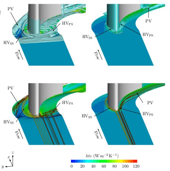
This Tecplot 360-generated image shows an endwall contour created by the Institute of Aerospace Thermodynamics researchers (left column) and compares it to a baseline flat endwall (right column).
Tecplot 360 Used as CFD Post-Processor
To find the most beneficial endwall geometry, Winkler and his associates analyze many different possible geometries by conducting CFD simulations of gas flow around the endwall and determining the heat-transfer from the flow to the endwall. The results of these CFD simulations are post-processed with Tecplot 360, a leading data visualization and analysis software tool developed by Bellevue, Wash.-based Tecplot Inc.
First released in 2014, Tecplot 360 is the most memory-efficient CFD post-processor available for desktop computers, requiring 92% less memory than earlier versions when loading modern high-fidelity CFD solutions.
With Tecplot 360, CFD engineers are now able to load and analyze data once reserved for only the largest high-performance computing centers. In the case of the Institute of Aerospace Thermodynamics, the data files are generally between 1.5 and 2.5 gigabytes. The software’s industry-leading speed – both computational and rendering — is achieved through Tecplot’s proprietary SZL technology, which is a combination of deferred data loading, exhaustive parallelization, and many other code optimizations.
“With Tecplot, we visualized how the flow looks using streamlines and vortex visualization, and what the temperature distribution on the endwall looks like due to this flow,” Winkler said. “In this vein we could find an optimum geometry – one that has a favorable flow around it and causes the lowest possible temperature of the part.” A lower temperature needs less cooling air to protect the part. Needing less cooling air improves the efficiency of the gas turbine. This will result in gas turbines that are more fuel-efficient and help to reduce pollutants, which are the ultimate goals of the project.
A Unique Approach Called the Ice Formation Method
To create the endwall geometries that are subsequently investigated with CFD simulations, Winkler and his colleagues used a very unique approach called the Ice Formation Method (IFM). The Institute has a water-channel test facility with a row of turbine blades. The researchers can cool the endwall of this blade row to temperatures below the freezing temperature of water. They then setup a water-flow over the cooled endwall, which results in ice layers that grow on the cooled wall. These ice layers interact with the flow until they reach steady-state and, therefore, an optimal shape.
“We then digitize these ice contours by means of a laser scanner and use them in CFD simulations where we check how these contours alter the flow-field and hence also the temperature distribution,” Winkler added. “This IFM method is a natural optimization approach that yields contours optimized with respect to energy dissipation and thus heat-transfer to the endwall.”
These complex CFD simulations are only useful, Winkler acknowledged, when the data is visualized using powerful post-processing software like Tecplot. “The real benefit of any software package is increased efficiency and productivity,” Winkler opined. “Tecplot 360 excels in this area by providing quick visualization and judging of flow simulations, and scripting tools that let me look at the same things for different flow simulations. And just as important, the software is easy to use.”
Additional information about the University of Stuttgart’s Institute of Aerospace Thermodynamics can be found at www.uni-stuttgart.de/itlr/.