


 MENU
MENUContributed by: Dr. Craig Hunter, NASA Langley Research Center
Noise Sources in a Jet Plume
The jet plume in Figure 1 originates from a bypass ratio (BPR) typical of a transport aircraft.

Figure 1. Noise sources in a jet plume visualized with Tecplot 360.
There are numerous frequencies of noise. The human ear is sensitive to noise from 20Hz – 20kHz. When full scale (9 times larger), the noise shown in the plot would be about 1400Hz, in the range of noise that annoys people.
The observer (or a microphone) can be at numerous angles relative to the jet engine. The inlet angle is measured from the front of the engine. Zero would be pointing ahead, 90 degrees to the side, and 180 degrees points downstream in the direction of the jet exhaust.
Concerns About Airport Noise
When Denver International Airport (DIA) joined the nation’s commercial air transport system in 1995, property owners in rural Adams County, a community 15 miles east of DIA, were concerned about the increase in noise that accompanied the new airport. A quick remedy to DIA’s noise problem is re-routing arriving and departing aircraft around populated areas. As the nation¹s fifth busiest airport, however, DIA quickly experienced delays. Course changes would cause airplanes to stack-up waiting their turn to land.
Other possible solutions are being studied nearly 2,000 miles away at the coastal city of Hampton, Virginia. Hampton is the home of NASA’s Langley Research Center, an 800-acre facility where 3,500 professionals are involved in cutting-edge aerospace technology. Among the specialists at NASA Langley are aerospace engineers and acoustics scientists. They work to make the skies quieter by designing technologies and procedures to reduce noise in engines, aircraft structures and areas around airfields.
Using CFD to Optimize Noise Reduction
Dr. Craig Hunter is one such aerospace engineer. A NASA Langley employee since 1997, Dr. Hunter specializes in aeroacoustics, jet noise prediction, and aerodynamics. He studies the effects of airflow on advanced aircraft concepts, an engineering discipline known as aerodynamics. A member of NASA Langley’s Configuration Aerodynamics Branch (CAB), Dr. Hunter knows the use of computational fluid dynamics (CFD) is a critical technique in simulating aerodynamics. CFD lets him look at airflow in various ways.
Typically, engineers test noise reduction concepts in an acoustic test lab, a wind tunnel, or in a flight test. These approaches are time consuming, costly, and possibly even dangerous. Using CFD and other simulation tools they can quickly evaluate, understand, and optimize potential noise reduction concepts on a computer. Using a CFD-based approach, they can look at several noise reduction concepts a week, and gain volumes of information – more than could ever be obtained in an experiment.
Originally written in FORTRAN and run on legacy UNIX workstations and supercomputers, Dr. Hunter recently ported one of NASA Langley’s CFD applications, called USM3D, to an Apple PowerMac G4 running Mac OSX. USM3D is part of NASA Langley’s Tetruss CFD system, a suite of computer programs for aerodynamic analysis and design.
Tecplot 360 Post-Processing
Tetruss users need a tool that allows them to see the flow field, understand it, and communicate the results to others. For that, Dr. Hunter turns to Tecplot 360.
Advanced Tailless Fighter Model
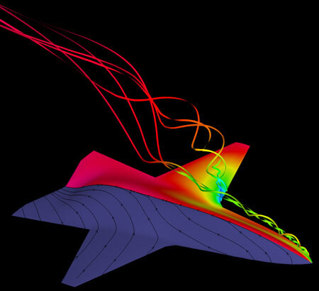
Figure 2: Tetruss results visualized with Tecplot 360.
A control effector is any type of device that provides maneuvering control on an aircraft. Conventional (mechanical) control effectors include flaps, ailerons, elevators, and rudders.
In the CAB at Langley, engineers look at advanced and unconventional control effector concepts – things like bumps that form on the aircraft skin, porous panels that alter surface loading, and smooth, continuous control surfaces that use advanced, smart materials.
The ultimate goal is an aircraft with a continuous or fixed outer moldline, that can maneuver as well or better than an aircraft with conventional mechanical controls. The benefits are lighter weight, better performance, and positive impacts on survivability, stealth, and observability.
Efficient and Versatile Tetruss CFD Tool
In addition to USM3D, Tetruss consists of an unstructured grid generation package and several other tools and utilities. Tetruss was developed at NASA Langley in the mid-1990s to bring the state-of-the-art in the field of CFD to a higher level of usefulness.
The Tetruss suite, originally planned for internal use only, gradually evolved into an efficient and versatile CFD tool, used by hundreds of engineers and scientists throughout government, industry and academia. The primary focus is in aerospace, but Dr. Hunter said “we have quite a few non-aerospace customers in industries such as automotive, bio-medical, and civil engineering.” In a cooperative effort, the U.S. Air Force Research Laboratory worked with NASA Langley to port the rest of Tetruss to Mac OS X. The result, Dr. Hunter believes, is the first complete CFD analysis software for Mac users.
Post-Processing with Tecplot 360
Dr. Hunter concedes that Tetruss is only as useful as the software used to post-process the CFD solution. In other words, Tetruss users need a tool that allows them to see the flow field, understand it, and communicate the results to others. For that, Dr. Hunter turns to Tecplot.
Tecplot is an ideal tool for engineers and scientists working with large data sets created by numerical simulation software like Tetruss. Tecplot 360 is available for computers running Windows, Mac OS X, Linux, and most versions of UNIX.