![]()
Addition of Disturbance Field Creates More Realistic Piloted Simulation Environment for Increased Safety and Lower Training Costs

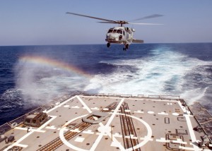
An SH-60B Seahawk helicopter approaches the USS Lassen. (U.S. Navy photo by Mass Communication Specialist 2nd Class Matthew R. White/Released)
Flying a helicopter has often been compared to balancing on one foot while standing on a beach ball—and that’s just over land. Now imagine balancing on a beach ball that’s on a funhouse floor in the middle of a nor’easter. That’s what a landing at sea can be like. The pilot must put the craft down on a ship that’s rising and falling with the swell of the sea, while being buffeted by the turbulence created by their machine’s rotors, other helicopters, the weather, and the ship’s air wake. No wonder pilots spend so much time in simulation training to develop and maintain their skills. That’s also why it’s vital that pilots sharpen their skills in the most accurate, real-time simulations possible. Continuum Dynamics, Inc. (CDI), a research firm specializing in fluid mechanics and dynamics, is doing its part to deliver a truly realistic, simulated training environment. Specifically, the company is using new computational fluid dynamic (CFD) methods with the aid of Tecplot 360 to create the first commercial ship air wake database for use in U.S. Navy helicopter trainers.
“Before we came along, there were no commercially-generated ship air wake databases in Navy flight simulators,” says Dr. Glen Whitehouse, CDI researcher. “Using traditional CFD approaches to develop those databases was an expensive and intractable challenge. You might see those traditional methods in a research environment, like the Navy, that could use a supercomputer to develop some of ship air wake databases. But it was very impractical, very expensive.”
The CDI air wake database can be interfaced with pilot training simulation equipment, including the MH-60R trainer developed by CAE USA for the U.S. Navy in Orlando, Florida. It ultimately allows pilots to experience the disturbance field in a flight simulator for the very first time, moving the simulated environment a step closer to providing real-time experiences.
“Until now, outside of a few research simulators and a trainer built by CAE Canada, that disturbance field has been represented with empirical models in commercial simulators,” says Whitehouse. “For our industry, that is the new thing added here.”
The CDI Approach to the Disturbance Field Issue
Technically, the CDI approach uses a hybrid CFD method to predict the spatially- and time-varying flow field. The core computational method combines an efficient, robust Cartesian grid-based Euler flow solver coupled with CDI’s VorTran-M wake module to preserve vorticity. This wake module minimizes the numerical diffusion present in conventional volumetric CFD methods, diffusion that causes non-physical smearing of vortices unless very high grid densities and high order methods are used. The hybrid approach produces high-fidelity results with lower grid densities that can be calculated more efficiently, and the reviews so far have been excellent.
“When evaluating a new simulator, the Navy brings in test pilots to fly all the scenarios and give a thumbs-up or thumbs-down. After all the technical reviews, the final say goes to a pilot as to whether it’s good enough or not,” says Whitehouse. “We got that approval a few months back and it was pretty exciting. Pilots flew the gamut of Navy missions, and thought that the simulation was realistic enough to enter service providing a high-fidelity training solution.”
Whitehouse says a small, nimble company like CDI can develop the necessary technology more quickly using modest computer resources to improve the level of physics embedded in the simulations, ultimately creating a better trainer.
“It just took too long, required too large of a computer to do this in an industry setting,” says Whitehouse. “The technology we’ve developed really has enabled a small company like ours to do this type of work. CDI has mapped 190-plus different permutations, with more on the way, essentially rewriting the industry database for helicopter air wake information.”
Tecplot 360 in the Mix

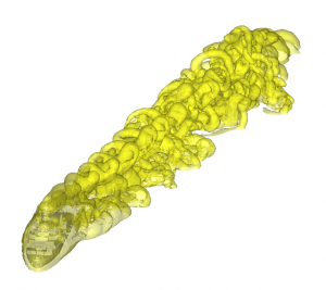
A computed ship air wake for a LPD-4 class ship (image credit: Continuum Dynamics)
CDI used Tecplot 360, a complete CFD visualization tool, to build the database and gain a better understanding of the physics underlying the air wake of a ship. The visualization software not only helped analyze and graphically render the data, it also helped cut the cost of deriving that data.
“You can view that as improving safety because you are reducing risk to the pilot’s life when they are training,” Whitehouse says. “That is the ultimate goal.”
Tecplot 360 allowed CDI to graphically render the data for better analysis, as well as to check and double-check data, especially for previously-undetectable data. For example, CDI uses Tecplot 360 to measure tip vortices, rendered visually as an intertwined blue helix.
“I could extract data for each one of those vortices, such as the distance beneath the rotor, so I could compare it to experimental data,” said Whitehouse. “You can also see the vortex pairing, which was not something that had been predicted with CFD for a hovering helicopter before this point. You start to see new physics that have been observed experimentally, but that people maybe have had difficulty predicting.”
Tecplot 360 also makes it easy to graphically reproduce various predictions. “It’s easy to load the data into Tecplot 360 and look at it in different ways and from different angles, whereas that may not be as easy to do in other tools,” adds Whitehouse. “We can do a lot with Tecplot 360 to better understand what’s going on, and we also can directly interrogate our predictions.”
That helped enable CDI to convert this new approach, and its proprietary CFD solver, into a software library, allowing customers to couple it with their own solvers and thereby enjoy the benefits of the CDI technology without having to discard their own proprietary system and the knowledge it contains.
Pilot Safety Meshes with Cost-reduction

Blue helix model of a Caradonna and Tung Rotor (image credit: Andrew Line)
The ultimate goal for CDI is pilot safety. Using the air wake data gathered by CDI, real-time piloted simulators continue to improve, allowing pilots to truly feel and gauge the unsteadiness behind a ship in a simulated environment. Pilots using the most accurate real-time simulators develop a feel for this unsteady air, so that when they actually have to perform the maneuver of landing or taking off from a ship in motion, they know what to expect.
In addition to pilot safety, the idea of reducing cost is an overarching theme for CDI. The two goals are intertwined: the lower the cost of this or any new technology can be driven, the more pilots will have access to it in training.
“We have a new way to let you do it that lets you do it faster than you could before,” concludes Whitehouse. “Everything going through here shows you the advantages of our new approach over traditional methods.”
Using Tecplot 360 to visualize air flow, CDI’s ship air wake database has reduced the need for dangerous and often unpredictable hands-on experience required for helicopter pilots to hone their take-off and landing skills at sea. With improved flight simulators, pilots and their employers can enjoy a higher level of training safety, and graduate better-prepared pilots to real-time flying in less time.


