


 MENU
MENUAutomated CFD methods and independent tools help improve efficiency of vertical axis wind turbines, which can ultimately increase market viability of micro power devices
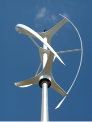
Darrieus wind turbine, Courtesy of Wind Turbine Zone
![]() Until recently, most research in wind energy technology has been focused on macro power generation devices like horizontal axis wind turbines. These massive devices, which are typically more than 100 meters in height and generate at least a megawatt of power, are well-suited for commercial interests in large industrialized regions in the US and Europe. This has been due in part to the fact that researchers could achieve greater levels of optimization with macro power devices on the limited funds that were available.
Until recently, most research in wind energy technology has been focused on macro power generation devices like horizontal axis wind turbines. These massive devices, which are typically more than 100 meters in height and generate at least a megawatt of power, are well-suited for commercial interests in large industrialized regions in the US and Europe. This has been due in part to the fact that researchers could achieve greater levels of optimization with macro power devices on the limited funds that were available.
Thanks to the US government’s increased commitment to green technology, however, quite a bit more research funding has begun flowing into micro power generating devices like vertical axis wind turbines. Small, quiet, and easy to install, vertical axis wind turbines operate well in fluctuating turbulent wind conditions like those found around buildings in cities, and suburban or urban areas. Rotating around an axis that’s perpendicular to the wind, they can take wind from any direction, consistently outputting a few kilowatts of power.
“This has relevance in the US, especially for people who want to lower their carbon footprint using personal green energy solutions,” says Travis Carrigan, who recently received his M.S. in aerospace engineering from the University of Texas at Arlington. “But it’s even more significant for the developing world, where you need to find many ways of bringing power to more rural, hard-to-reach areas that aren’t supported by any sort of infrastructure.”
Carrigan’s thesis, Aerodynamic Shape Optimization of a Vertical Axis Wind Turbine, proved that researchers could improve the efficiency of a Darrieus wind turbine by at least 7% using independent wind turbine CFD post-processing tools and automated methods for optimizing the blade shape.
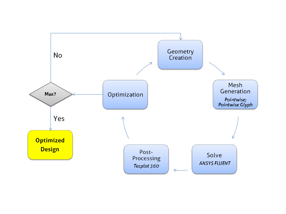
The Optimization Process
Optimization process. Any independent tools can be implemented in the optimization process, but for this particular problem, Carrigan selected Pointwise for the geometry generation and meshing, ANSYS FLUENT for the solver, and Tecplot 360 for the post-processing. Being able to plug in a specific tool for a specific task allows the design engineer to use the best tool for the task and yield the greatest optimization results.
“My motivation was to maximize the efficiency of a vertical axis wind turbine by allowing the blade shape to change as the optimization progressed,” says Carrigan, now a technical sales engineer with Pointwise, Inc., which creates software used for grid generation and preprocessing for computational fluid dynamics (CFD). His objective was to maximize blade efficiency, reduce reliance on designer experience—which varies widely—and ultimately reduce design time and cost.
“There’s quite a large design community building these machines in their backyards or garages,” says Carrigan. “Reducing the design cycle by using an automated computational framework could really reduce research cost by eliminating countless hours spent manually constructing many physical or computational models and analyzing each one through a design of experiments or exhaustive search technique. I also wanted to incorporate independent analysis tools rather than use a single package because I wanted the freedom to pick the best tools for a given task while also being flexible and having the ability to work well with the tools that I chose.”
Animation. The results are more dramatically visible in this animation generated in Tecplot 360.
Optimization loop: Independent tools for more control, consistent and reliable results
In developing his idea and optimization process, Carrigan and his advisor determined that it would be best to integrate a variety of independent tools for each step from creating the geometry and the mesh, to solving, post-processing, and optimization.
He began by using Pointwise to create the geometry, and Pointwise’s scripting language, Glyph, to tie it all together and create the mesh. Since this was a fairly straightforward geometry, Carrigan initially thought a fully structured mesh would give most accurate and reliable results. But after conducting a subtle yet important survey that included a mesh-dependency study of different mesh resolutions and mesh types, he found that the solution was most sensitive to the boundary layer and a hybrid topology was easier to automate using fewer cells.
This represented a significant time-savings, especially in the case of an unsteady simulation such as this one. The smaller overall grid size coupled with the larger cell sizes and time-step size may have represented a small savings if running a couple of simulations, but it proved to be very significant when running the hundreds of simulations that Carrigan would need to run.
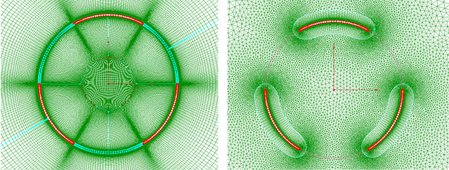
Mesh Topology. Carrigan initially thought a fully structured mesh (L) would give most accurate and reliable
results. But after a subtle yet important survey that included a mesh-dependency study of different mesh
resolutions and mesh types, he determined a hybrid topology (R) was easier to automate using fewer cells.
“The other advantage to the hybrid approach is you can easily automate the meshing process,” Carrigan says. “Reliable and robust meshing is a must for optimization and if you’re analyzing hundreds or thousands of blade geometries this can be accomplished more easily using a hybrid meshing approach.”
For the optimization algorithm, Carrigan used an in-house differential evolution algorithm which is a stochastic direct search method where the design parameters are represented by floating point values rather than binary strings.
This is an attractive choice for design optimization where the characteristics of the solution space may not be known beforehand. Using ANSYS FLUENT as the solver, Carrigan next turned to Tecplot 360 to post-process the wind turbine CFD data and visually evaluate the vortex shedding following the optimization. After running the optimization, the leading edge vortex shedding occurring for the baseline geometry had been eliminated resulting in higher overall average torque and a 7% increase in efficiency.
“Automating this portion of the process should help designers get these small wind turbines to market much more quickly,” says Carrigan. “You can use any independent tools, but for this particular problem we selected Pointwise for the geometry generation and meshing, ANSYS FLUENT for the solver, and Tecplot 360 for the wind turbine CFD post-processing,” he adds. “Being able to plug in a specific tool for a specific task gave us the ability to use the best tool for the task and yield the greatest optimization results.”
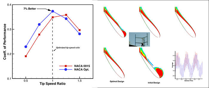
Results. After running the optimization, the results showed that the leading edge vortex shedding occurring for the baseline geometry had been eliminated, resulting in higher overall average torque and a 7% increase in efficiency.
For a more thorough technical discussion and demonstration of Carrigan’s automated process, watch the recorded Webinar on YouTube Parametric Optimization for Vertical Axis Wind Turbines Design Using Independent CFD Tools.