


 MENU
MENUCase Study: Tecplot Chorus integrates with KARALIT CFD to save time with mesh-free CFD simulations and analyses
The Immersed Boundary (IB) methodology, a mesh-free technique for running CFD simulations, has been around since the 1970s. Instead of running Navier-Stokes equations on grids that conform to the shape of an object, as is done with meshing, the IB technique immerses a CAD model of the object into a Cartesian grid and then integrates the equations into that Cartesian grid.
The promise of IB was that it could eliminate the time spent on the set-up and generation of a mesh. It also did not require morphing, which can deteriorate the mesh, or re-meshing the computational domain when the geometry is changed. This technique was hampered, however, by the lack of an effective numerical theory for generating the cells that intersect with the object’s surface and was discarded in favor of mesh generation techniques.
As geometries became more complex and the size of the data started to increase exponentially, so did the time it took to generate the meshes, and interest in Immersed Boundary methodologies was renewed.
Among the first to commercially and successfully harness the power of this time-saving methodology is KARALIT, a start-up company headquartered in Pula, Italy. KARALIT provides a CFD software that is based on the IB technique. It works seamlessly with Tecplot Chorus, a software tool that integrates CFD post-processing, field and metadata management, and analytics tools into a single environment.
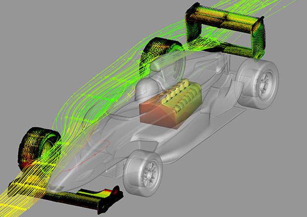
Engine cooling case evaluated using the Immersed Boundary method with KARALIT CFD and Tecplot Chorus. Formula race car provided courtesy of Tatuus Racing.
Durrell Rittenberg, Tecplot Inc.’s vice president of product management, and Sohail Alizadeh, director of UK and Ireland sales and operations at KARALIT, recently demonstrated the speed at which the design of a Formula Renault Tatuus 2000 race car (provided courtesy of Tatuus Racing) could be assessed using both tools.
In this demonstration Rittenberg and Alizadeh took a little more than an hour to evaluate the performance of the car’s rear wing by changing the geometry and dropping the wing by 10 centimeters, opening the engine bay ventilation flow and external dynamics of the car to observe cooling of the engine, and examining the overall exterior aerodynamics.
“We were able to show that, by combining this mesh-free IB methodology with Tecplot Chorus, you can reduce the time spent running CFD simulations and analysis by an order of magnitude,” says Rittenberg.
“In other words, we demonstrated that you can use these two tools to run the CFD, look at and analyze many different solutions, and confidently make design decisions in a few hours instead of weeks.”
KARALIT CFD and the Immersed Boundary Method
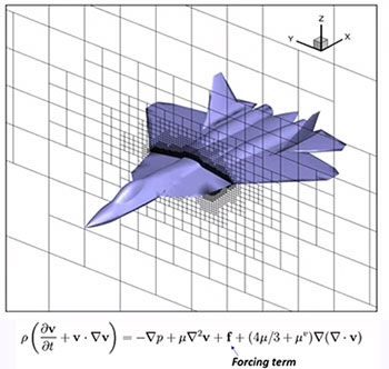
With the Immersed Boundary (IB) method, the object’s geometry is immersed directly into a Cartesian mesh.
Alizadeh explains the process for setting up the geometry and running the solution.
“You basically have a complex geometry and you need to run a simulation of it on a computational grid. In KARALIT the grid is a non-isotropic Cartesian unstructured grid,” he says. “The grid needs to sense the complex geometry as it passes through and then the CFD simulation needs to know the boundary conditions, which is where the geometry intersects the grid.”
The grid is categorized into three parts, which don’t appear in traditional CFD:
- Fluid flow
- Boundary cells
- Ghost cells
Ghost cells are reflected as mirror points in the fluid and, during the calculation, the field values are interpolated to the mirror cells. The ghost cells solved during calculation can be set at the correct value so that the resulting boundary condition is forced on to the calculation.
“What that means is that—implicitly and automatically in the background—the entire process of absorbing the geometry and boundary conditions takes place during the simulation and calculation,” says Alizadeh. “It results in a very simple workflow: the CAD geometry is imported into the code (SDL in this case), you set up a few parameters, and run the solution. KARALIT outputs to PLT files, so that it can be easily imported by Tecplot software products.”
KARALIT is set up for parallelization, which means it can do hundreds of nodes, Alizedah notes, adding that the size of the cases that can be run are limited only by the size and memory of the computer.
Analyzing Results Using Tecplot Chorus
Once the simulation was run, the results and the complex geometries could be imported into Tecplot Chorus for fast, accurate analysis and comparison across multiple design candidates. As mentioned earlier, Tecplot Chorus integrates a powerful set of CFD post-processing, field and metadata management, and analytics tools into a single environment, reducing the time it takes to analyze multiple designs in most cases from several weeks to a few hours.
In this demonstration, Rittenberg and Alizadeh were able to quickly determine that that the air pressure on the rear wing of the race car was less in the lowered position than in the original position.
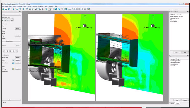
Tecplot 360 shows a side by side comparison of the fluid dynamics, including pressure fields and streamtraces, of the race car’s base wing in the lower position (left) and upper positon (right).
“The real win here is that we can quickly look at multiple design candidates, evaluate the results, and identify the optimal design,” says Rittenberg. “We are able to skip the busy work. There was no meshing, no macros to write, no loops, and we didn’t have to fuss with the data, among other things. We just looked at the physics and made the design decisions.”
Combining the CFD / IB methodology with Tecplot Chorus works most effectively with complex geometries that have a lot of intricate surfaces, says Rittenberg. Building a project out of even a simple number of solutions can be very convenient when you want to interrogate different views. Tecplot Chorus allows users to do this without generating too many macros and loops, he says, and it allows users to interactively evaluate many key integrated quantities.
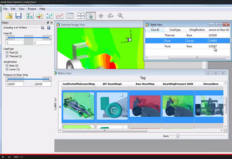
This Tecplot Chorus project shows pressures on the rear wing for two cases where the wing geometry has been 1) left in its original position and 2) lowered. This analysis shows that the air pressure on the rear wing in the lowered position is slightly less than the air pressure on the rear wing in the original position.
“You can do so many things with Tecplot Chorus,” Rittenberg adds. “Synchronize styles across multiple solutions, quickly interrogate a set of solutions, look for deltas, and identify what may be driving the physics. You can look at a hundred different solutions at a glance. That, combined with the mesh-free Immersed Boundary method, brings us back to our finding: that you can reduce the time spend running CFD simulations and analysis by an order of magnitude. And that’s a big number.”
Video Demos
Watch how you can tap into time-savingm mesh-free CFD simulations with KARALIT and Tecplot Chorus. These videos demonstrate how the Immersed Boundary method and CFD simulation results are evaluated in Tecplot 360 and Tecplot Chorus.