


 MENU
MENUVisualization of Higher-Order Elements – Part 3: Isosurface Algorithms
This blog was written by Dr. Scott Imlay, Chief Technical Officer, Tecplot, Inc.
In this blog I’ll be discussing our research into isosurface algorithms for higher-order finite-element solutions. The first blog on this topic was A Primer on Visualizing Higher-Order Elements and the second was on the Complex Nature of Higher-Order Finite-Element Data.
Big cells beget little cells
That model their complexity
And little cells have smaller cells
That we choose selectively
In the second blog, I described how the isosurface passing through a linear tetrahedra is a simple plane described entirely by its intersections with the edges. Since the solution varies linearly along the edges you can calculate these intersections very quickly. You can also quickly exclude edges based on the range of the nodal values at either end of the edge. If the isosurface value is greater than the maximum node value, or less than the minimum node value, no further computation is needed. In this way, the vast majority of the edges can be excluded from further computation by a couple of simple floating-point compares. This, among other optimizations, make this technique very fast.
Isosurfaces in a Quadratic, Higher-Order Element
In comparison, an isosurface in a quadratic, or even higher-order, element can be quite complex. The isosurface is not, in general, planar and it doesn’t even have to intersect the edges or surfaces of the element (see Figure 2). You can have isosurfaces that are entirely contained within an element like little islands. How do we extract these isosurfaces?
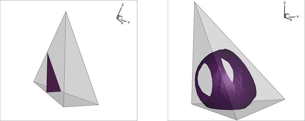
Figure 1. Isosurface in linear tetrahedron (left). Figure 2. Isosurface in quadratic tetrahedron (right)
Nearly all visualization techniques for higher-order isosurfaces involve subdividing the higher-order element into a large number of linear sub-elements. The variation of the solution across these sub-elements approximates the non-linear solutions and the approximation error decreases as the number of sub-elements increase. Once you have the sub-element, you can use existing isosurface algorithms for linear elements to extract an approximate non-linear isosurface. Sounds easy, right?
Visualization Techniques for Higher-Order Isosurfaces
It is fairly easy to implement an algorithm where all higher-order elements are sub-divided into a large number of linear elements. A quadratic tetrahedra, for example may be divided into eight sub-tetrahedra using the existing ten nodes. This sub-division is shown in Figure 3. Each of those sub-tetrahedra may be further subdivided into eight sub-sub-tetrahedra by creating new nodes at the edge centers, interpolating to those nodes using the full quadratic element basis function, and subdivide as done for the original element. This process can be repeated until the non-linear isosurface is sufficiently resolved.
Unfortunately, the number of sub-cells grows exponentially: after the first sub-division it is eight sub-cells, after the second level of sub-divisions it is 64, after the third level of sub-divisions it is 512, and so on. If you start with 500 thousand higher-order cells you will have 256 million linear sub-cells after three levels of sub-division. It is not cheap to create those 256 million linear sub-cells!
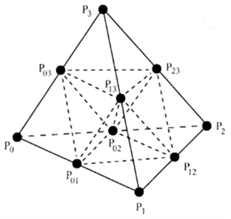
Figure 3. Tetrahedron sub-division.
Most of my research has been on optimizations to make this faster. Specifically, are there simple tests that will allow us to eliminate cells early in the process?
For example, for linear elements, we compute the min/max range of the isosurface variable for all nodes in the element, and we exclude cells where the isosurface value is not in that range. We do this because the cell extrema (min’s and max’s) in linear cells are guaranteed to be at the nodes.
Unfortunately, for most basis functions the extrema in a higher-order cell is not generally at the nodes but may be anywhere within the cell. If we can find a way to quickly exclude higher-order cells, we can significantly reduce the computational cost and memory usage of the subdivision process.
Optimizing the Isosurface Algorithm
It turns out you can eliminate many cells based on the min/max values of the isosurface variable at the nodes. A heuristic formula that seems to work is to keep any cell where the isosurface value satisfies this formula:
2φ_min-φ_max<φ_iso<2φ_max-φ_min
I wish I had a mathematical proof that this formula always works, but it has worked in all the cases I’ve tested so far. This formula basically has a buffer equal to the range of the isosurface variable in the non-linear cell. The same formula, with smaller buffers, is applied to the sub-cells at each level of recursion. That is, the formula is also applied when sub-dividing the sub-cells, and again when subdividing the sub-sub-cells, but the size of the buffer on the isosurface variable range is smaller each time.
Selectively subdividing elements based on the formula above dramatically reduces the cost of extracting higher-order isosurfaces. In Figure 4 you can have four levels of subdivision for an isosurface of constant radius from a point. By the fourth level of subdivision, all but 8,617 out of a possible 663,552 sub-cells have been excluded. Over 98.7% of the sub-cells have been discarded and further computations should be nearly a factor of 100 faster!
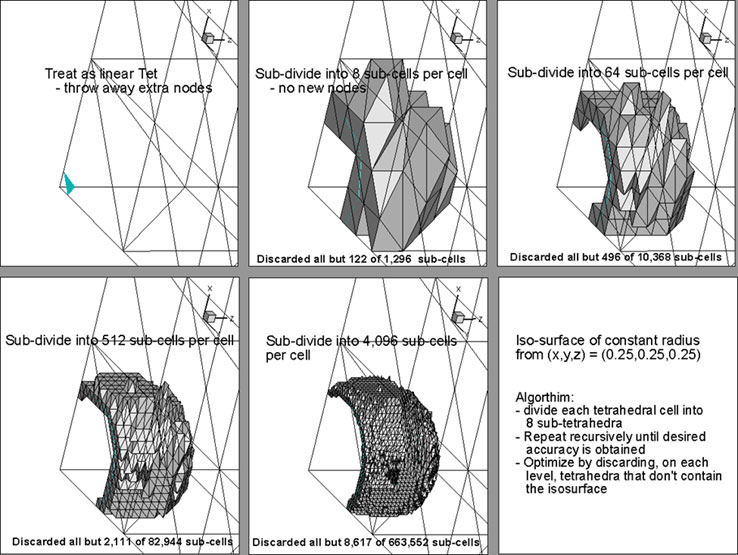
Figure 4. Selective subdivision for quadratic tetrahedral isosurface extraction.
Figure 5 shows the extracted isosurface at various levels of subdivision. Four levels of subdivision are sufficient to create a very smooth isosurface.
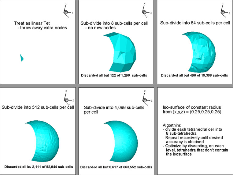
Figure 5. Quadratic tetrahedral isosurface with increasing levels of subdivision.
In my next blog, I will discuss the results of our research into higher-order finite-element curved surface visualization algorithms. See all blogs on higher order elements.
Subscribe to Tecplot
Get all the latest news from Tecplot, Inc.