


 MENU
MENUThis blog was written by Dr. Scott Imlay, Chief Technical Officer, Tecplot, Inc.
He glides to landing
Feathers flare and wings unfurl
Flapping to his perch
As an undergraduate in Aeronautical and Astronautical engineering in the early 1980s, I worked at the University of Washington Aeronautical Laboratories (UWAL) wind tunnel. It was an older low-speed wind tunnel, but it had a large 8×12 foot cross section and was used heavily by Boeing to explore landing and take-off configurations for their new 757, 767, and 737-300 aircraft designs. While the UWAL wind tunnel was relatively inexpensive, it was still very costly and Boeing spent many thousands of hours tweaking flap and slat positions, trying to find the ideal high-lift configuration.
Boeing spent so much time and money at UWAL because high-lift performance, stability, and control are critical to the success of a new aircraft. As an airplane slows from cruising speed to landing speed, it must increase its angle of attack to create sufficient lift to counter its weight. At some point the angle of attack becomes so great that the boundary layer separates from the wing and the lift actually decreases. This is wing stall, and the lift coefficient (CL) at which this occurs is called CLmax. Flaps and slats increase CLmax so that the airplane can fly (and land) at a lower speed.
High Lift Prediction Workshops at SciTech
Aircraft designers would like to minimize wind-tunnel costs by using CFD to analyze the aerodynamics of aircraft in high-lift configurations. This is currently being done to some extent, but the complicated geometries require very dense grids which make it costly. Also, the presence of boundary-layer separation reduces confidence in the results. To better understand the issues, the first AIAA CFD High Lift Prediction Workshop was held in 2010. There have been three other workshops held since then, with the last held at the SciTech meeting earlier this month. These are some of my impressions from the last workshop. See all High Lift Prediction Workshops.
The workshop had six Technical Focus Groups (TFGs). The first was on geometry and mesh preparation – not a simple thing for a configuration with so many connected pieces – and the remaining five explored different solution methodologies. Solver methodologies include fixed-grid Reynolds-averaged Navier-Stokes (RANS), mesh-adapted RANS, high-order discretization, hybrid RANS-LES (large eddy simulation), and wall-modeled LES.
Goal of the High Lift Prediction Workshops
The goal of the high-lift prediction workshop is to determine “What CFD solution methodology(ies) currently provides the best/most-consistent approach to predicting (a) increments due to flap deflection, and (b) maximum lift?” The workshop ran for a full day and there was a lot of information presented. I will focus on the “maximum lift” portion of the goal.
Workshop Results
The result? RANS solutions typically predicted too much outboard separation at CLmax, at least with the Spalart Allmaras (SA) turbulence model. Figure 1 shows the results for one of the cases. Note that the outboard region should have “pizza slice” shaped separation regions from the slat brackets (point of the pizza slice) to the trailing edge (wide portion of the pizza slice). The RANS-SA CFD solution, on the other hand, shows a much broader region of separation. Even though the RANS-SA CFD solutions do a reasonable job of predicting CL, they are very inconsistent at predicting the pitching moment. This is a problem, because the pitching moment has a big impact on the behavior of the aircraft when the wing stalls. Aircraft designers want the nose to naturally pitch down so that the airplane will recover from the stall, but you need accurate pitching moment predictions to get the desired result.
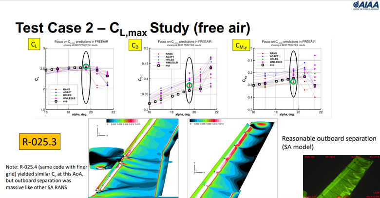
Figure 1. Typical RANS-SA result from the HiLftPW summary presentation.
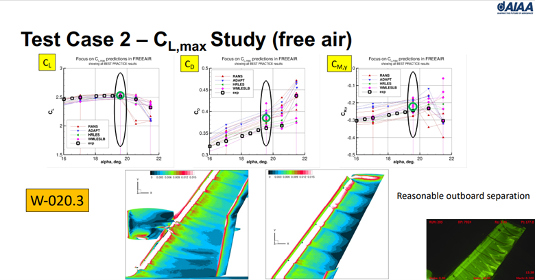
Figure 2. Typical wall-model LES result from the HiLftPW summary presentation.
High Lift Prediction Workshop Summary
So what does this all mean? It means that the most common CFD methodology currently used for analyzing high-lift configurations, Reynolds-averaged Navier-Stokes with a Spalart-Allmaras turbulence model, is problematic for predicting flows near CLmax. It over-predicts boundary-layer separation in the outboard region of the wing. In comparison, the less popular large-eddy simulation methodologies do pretty well.
My PhD advisor, Bob MacCormack, was fond of saying he would never fly in an airplane designed exclusively with CFD. It appears that sentiment is still valid, at least when it comes to aerodynamics near CLmax. It is possible that RANS would do better with another turbulence model, or even different variant of the Spalart Allmaras model, but those options were not studied in this workshop. It is also possible that aerodynamicists will need to switch to large eddy simulations to get accurate solutions in this flight regime. It looks like another high-lift prediction workshop will be required!
More Tecplot Resources on High Lift
- Analysis of Aerodynamic Workflows webinar
- Tail Strake Position Optimization for Generic Transport Aircraft case study
- Comparing a CFD Simulation with Experimental Data video tutorial
- External Flow – CFDA and Variable Calculation video tutorial